IPC 2581 vs. ODB++: Choosing the Right Data Exchange Standard for Your PCB Project
Author : Adrian September 19,how to make solder paste at home 2025Table of Contents
If you're deciding between IPC-2581 and ODB++ for your PCB project, you're likely looking for the best way to transfer design data to manufacturing. In short, IPC-2581 is an open standard, free for anyone to use, offering a single-file format for comprehensive data exchange. ODB++, on the other hand, is a proprietary format, widely supported but controlled by a specific entity, often requiring licensing for full access. For most modern projects, IPC-2581 is the better choice due to its openness and growing industry support, but ODB++ may still be necessary if your manufacturing partners prefer it. In this blog, we'll dive deeper into a PCB data exchange format comparison, exploring the differences between open standard vs proprietary formats, and guide you on choosing PCB data transfer options while highlighting ODB++ alternatives.
Introduction to PCB Data Exchange Standards
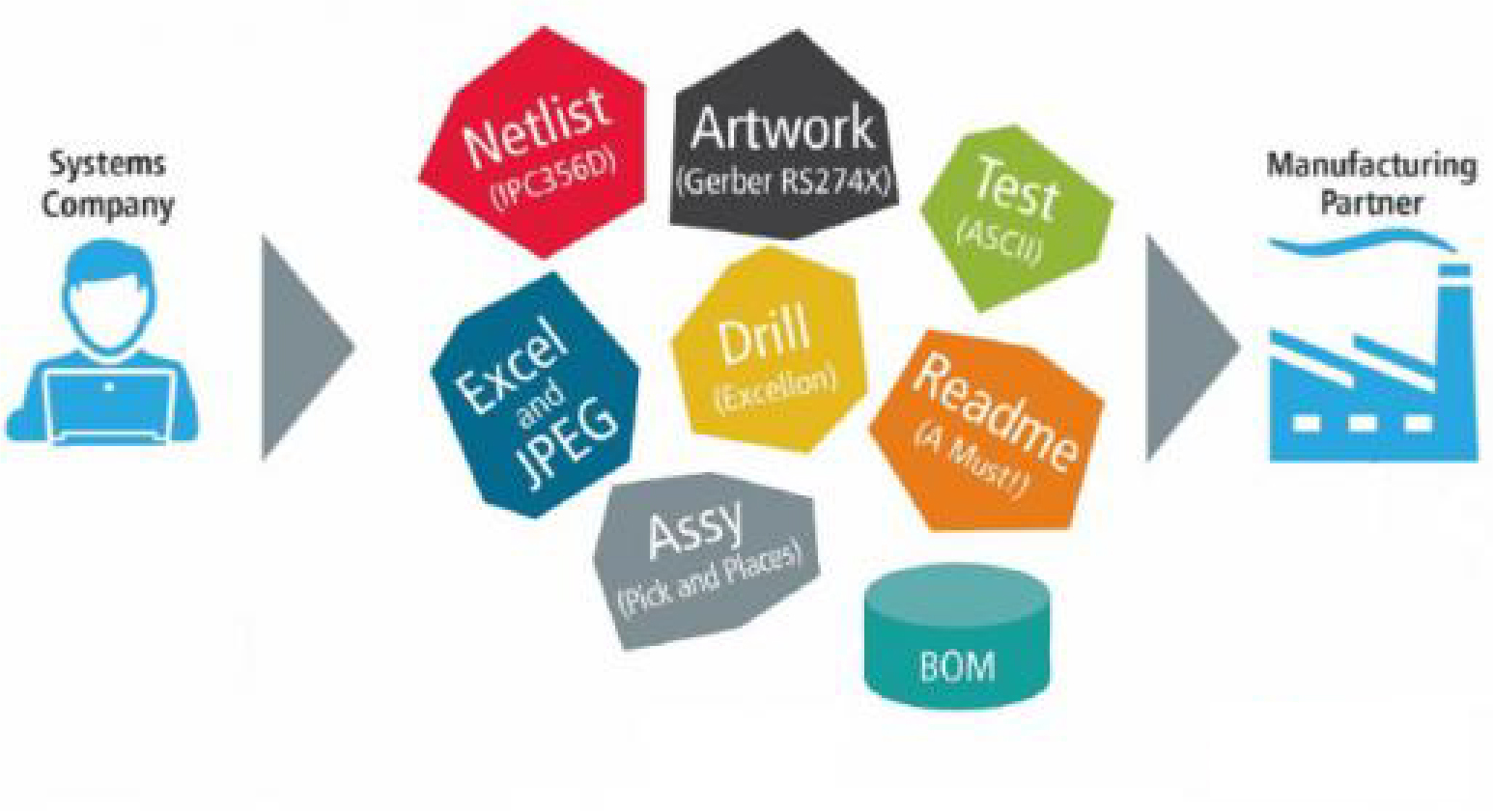
In the world of printed circuit board (PCB) design and manufacturing, seamless data transfer is critical. The files you send to your manufacturer must contain all the necessary information—layer stackups, component placements, netlists, and more—to ensure the board is built correctly. Two prominent standards for this data exchange are IPC-2581 and ODB++. Both formats aim to solve the challenge of transferring complex design data, but they differ significantly in their approach, accessibility, and adoption.
Whether you're a PCB designer, engineer, or project manager, understanding the strengths and weaknesses of each format can save you time, reduce errors, and improve collaboration with your manufacturing team. This blog will break down the key aspects of IPC-2581 vs ODB++, helping you make an informed decision for your next project.
What is IPC-2581?
IPC-2581 is an open standard for PCB data exchange, developed by the Institute of Printed Circuits (IPC). Introduced as a modern alternative to older formats, it aims to streamline communication between design and manufacturing by providing a single, comprehensive file format. This file includes everything needed for fabrication and assembly, such as layer data, drill information, bill of materials (BOM), and even test points.
One of the biggest advantages of IPC-2581 is that it’s an open standard. This means it’s free to use, and any software developer or manufacturer can implement it without licensing fees. As of recent years, adoption has grown, with many leading design tools and manufacturers supporting this format. For instance, it reduces the risk of data loss or misinterpretation, as all information is bundled into one XML-based file, making it easier to manage compared to multiple files required by older formats like Gerber.
Key Features of IPC-2581:
- Single-file format for all manufacturing data.
- Supports complex designs, including multi-layer boards and high-speed signals.
- Open standard, fostering collaboration and innovation.
- Reduces errors by eliminating the need for multiple file types.
What is ODB++?
ODB++ is a proprietary data exchange format originally developed by Valor Computerized Systems and now managed by a major industry player. It was created to address the limitations of older formats like Gerber by offering a more intelligent and comprehensive way to transfer PCB design data. Like IPC-2581, ODB++ consolidates design information into a structured format, including layers, components, and netlists, often in a single compressed file.
ODB++ has been widely used in the industry for decades and is supported by many design and manufacturing tools. However, because it is proprietary, full access to its specifications or implementation often requires licensing or specific software. This can create dependency on certain tools or vendors, which may not align with every project’s needs.
Key Features of ODB++:
- Comprehensive data in a structured format, often a single file.
- Long-standing industry adoption with extensive tool support.
- Proprietary nature may limit flexibility or increase costs.
- Well-suited for complex designs with detailed manufacturing requirements.
IPC-2581 vs ODB++: A Detailed PCB Data Exchange Format Comparison
Now that we’ve covered the basics of each format, let’s dive into a head-to-head comparison based on key factors that matter to PCB designers and manufacturers. This will help you weigh the pros and cons when choosing PCB data transfer standards for your project.
1. Open Standard vs Proprietary Format
The most significant difference between IPC-2581 and ODB++ is their accessibility. IPC-2581 is an open standard, meaning its specifications are publicly available, and anyone can implement it without cost. This openness encourages wider adoption and reduces dependency on specific vendors. It also allows for community-driven updates and improvements, ensuring the standard evolves with industry needs.
In contrast, ODB++ is a proprietary format. While it’s widely supported, its development and full implementation are controlled by a single entity. This can lead to licensing costs or restricted access to certain features, especially for smaller companies or independent developers. If your project prioritizes flexibility and cost savings, IPC-2581 may be the better choice.
2. Data Integration and Completeness
Both formats aim to provide a complete data package for manufacturing, but they approach this differently. IPC-2581 uses an XML-based structure, which is human-readable and highly organized. It can include detailed information like impedance control values (e.g., 50 ohms for high-speed signals) and specific material requirements for multi-layer boards (e.g., FR-4 with a dielectric constant of 4.2). This makes it easier to verify and modify data if needed.
ODB++ also offers a comprehensive dataset, often in a compressed format, which can handle complex designs with up to 100+ layers or high-density interconnects (HDI). However, because it’s proprietary, interpreting or modifying the data may require specific software, potentially creating bottlenecks if your manufacturing partner uses different tools.
3. Industry Adoption and Support
ODB++ has a long history of use, dating back to the 1990s, and is supported by a vast number of design and manufacturing tools. Many manufacturers prefer it due to familiarity and established workflows. For example, if your project involves high-speed designs with signal integrity requirements (e.g., differential pairs operating at 10 Gbps), ODB++ support is often readily available in legacy systems.
IPC-2581, while newer, is gaining traction rapidly. As of 2025, many modern design tools and manufacturers have adopted it, driven by the push for open standards. Its adoption is particularly strong in regions and companies focused on innovation and reducing vendor lock-in. If your project is forward-looking or involves collaboration across multiple partners, IPC-2581 could offer better compatibility in the long term.
4. Error Reduction and Efficiency
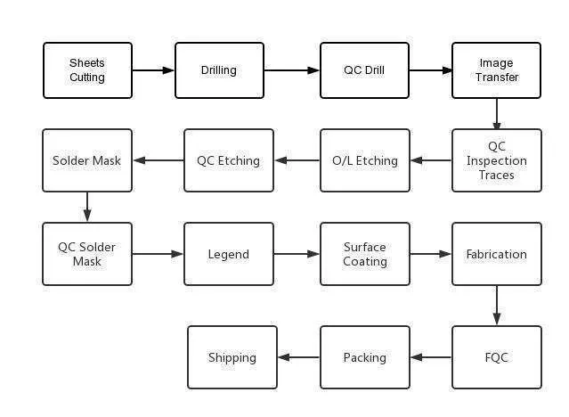
Both formats reduce errors compared to older standards like Gerber, which often requires multiple files (e.g., one for each layer, drill data, etc.). With Gerber, a missing file or mislabeled layer can delay production. IPC-2581 and ODB++ bundle all data into a single package, minimizing these risks. For instance, IPC-2581 can embed precise drill tolerances (e.g., ±0.05 mm) directly in the file, ensuring clarity for manufacturers.
However, IPC-2581’s open nature allows for better error checking by third-party tools, as its structure is accessible to all. With ODB++, error checking might be limited to licensed software, potentially slowing down the process if issues arise.
Choosing PCB Data Transfer: Which Format is Right for Your Project?
Deciding between IPC-2581 and ODB++ depends on several factors specific to your project and team. Here are some practical considerations to guide your choice:
- Manufacturer Preference:Check with your manufacturing partner. Many still prefer ODB++ due to its long-standing use, but an increasing number support IPC-2581. If your manufacturer uses older systems, ODB++ might be the safer bet to avoid delays.
- Design Complexity:For highly complex designs, such as those with 16+ layers or strict impedance requirements (e.g., 100 ohms for controlled lines), both formats work well. However, IPC-2581’s open structure may make it easier to customize or troubleshoot.
- Budget and Licensing:If cost is a concern, IPC-2581 avoids proprietary licensing fees associated with some ODB++ implementations. This can be a significant advantage for startups or small teams.
- Future-Proofing:IPC-2581 is positioned as the future of PCB data exchange due to its open nature and growing support. Choosing it now could prepare your workflow for upcoming industry shifts.
Exploring ODB++ Alternatives
If you’re looking for ODB++ alternatives due to its proprietary limitations, IPC-2581 is the most direct and modern option. However, there are other considerations depending on your project needs:
- Gerber X2/X3:While not as comprehensive as IPC-2581 or ODB++, newer Gerber versions include additional metadata like netlists. They’re widely supported but still require multiple files, increasing the risk of errors.
- Custom Formats:Some design tools offer their own export formats tailored to specific manufacturers. These can work well for niche projects but lack the universal compatibility of IPC-2581.
For most projects seeking an alternative to ODB++, IPC-2581 stands out as the best choice due to its openness, comprehensive data handling, and alignment with modern industry trends.
Benefits of Adopting IPC-2581 for Modern PCB Projects
As the industry moves toward open standards, adopting IPC-2581 offers several long-term benefits. It reduces dependency on specific vendors, lowering costs and increasing flexibility. Its single-file format simplifies data management, especially for complex designs with high-speed requirements (e.g., signal speeds up to 25 Gbps). Additionally, its growing support means you’re less likely to face compatibility issues as more tools and manufacturers adopt it.
For example, if your project involves a 10-layer board with strict signal integrity needs, IPC-2581 can embed all relevant data—such as trace widths of 0.1 mm and spacing of 0.15 mm—directly in the file, ensuring nothing is lost in translation during manufacturing.
Conclusion: Making the Right Choice for Your PCB Data Exchange
Choosing between IPC-2581 and ODB++ for your PCB project comes down to your specific needs, manufacturer preferences, and long-term goals. IPC-2581 offers the advantage of being an open standard, providing flexibility, cost savings, and future-proofing for modern designs. ODB++, with its extensive industry adoption, remains a reliable choice, especially for manufacturers with established workflows.
By understanding the differences in this PCB data exchange format comparison, you can make an informed decision that aligns with your project’s requirements. Whether you prioritize open standard vs proprietary formats or need ODB++ alternatives, evaluating factors like data integration, error reduction, and tool support will guide you to the best option. For most new projects, starting with IPC-2581 is a forward-thinking choice that positions you for success in an evolving industry.

The Role of Flux in PCB Wave Soldering: Selection, Application, and Residue Removal
March 16, 2026PCB wave soldering flux types include rosin, water-soluble, and no-clean options with varying activity levels for oxide removal and solder flow. This guide covers selection criteria, spray foam drop-jet application methods, residue removal processes, and alternatives like nitrogen blanketing to boost joint reliability and yields for engineers.
Article
Achieving Uniform Solder Fillets in PCB Wave Soldering: Process Control
March 16, 2026Achieve uniform solder fillets in PCB wave soldering with process control strategies. Optimize flux, preheat, wave height, conveyor speed for consistent fillet shape, height, and wetting balance. Includes visual inspection tips and troubleshooting for reliable through-hole assemblies. Boost quality in production.
Article
Optimizing Conveyor Speed for Efficient PCB Wave Soldering
March 16, 2026Learn PCB wave soldering conveyor speed calculation to manage dwell time, immersion depth, and throughput effectively. Electric engineers get practical steps, best practices, and troubleshooting tips for higher process efficiency and fewer defects in wave soldering operations.
Article
Understanding IPC Standards for PCB Surface Finishes: Ensuring Quality and Compliance
March 11, 2026Understand IPC standards IPC 4552 ENIG and IPC 4553 immersion silver for PCB surface finishes. Ensure compliance, enhance solderability, and prevent common defects to achieve reliable, high quality circuit boards.
Article
Miniaturization Challenges in PCB Assembly
March 11, 2026Navigate the complexities of high density interconnect PCB assembly and precise component placement. Learn to tackle miniaturization challenges, from tiny part handling to thermal stress, ensuring robust and reliable electronics.
Article
High Speed Routing Techniques: PCB
March 11, 2026Master high speed routing in PCBs to ensure signal integrity and minimize electromagnetic interference. Learn essential techniques for robust designs, from controlled impedance to differential pair strategies. Prevent performance issues and achieve reliable electronics.
ArticleGet Instant PCB
Quotations
Full-featured PCB
manufacturing service at low cost.


 相关文章
相关文章

 精彩导读
精彩导读

 热门资讯
热门资讯 关注我们
关注我们